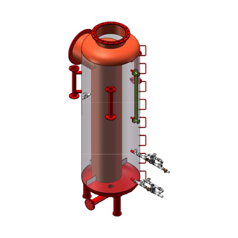
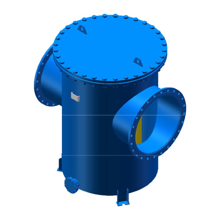
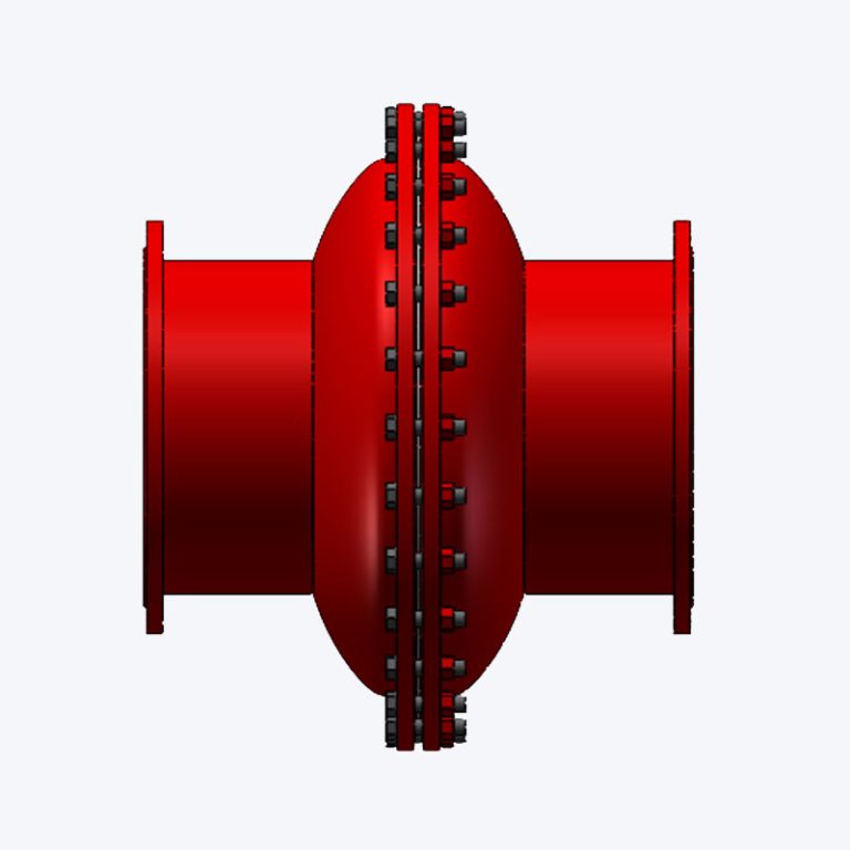
Product Brief Description
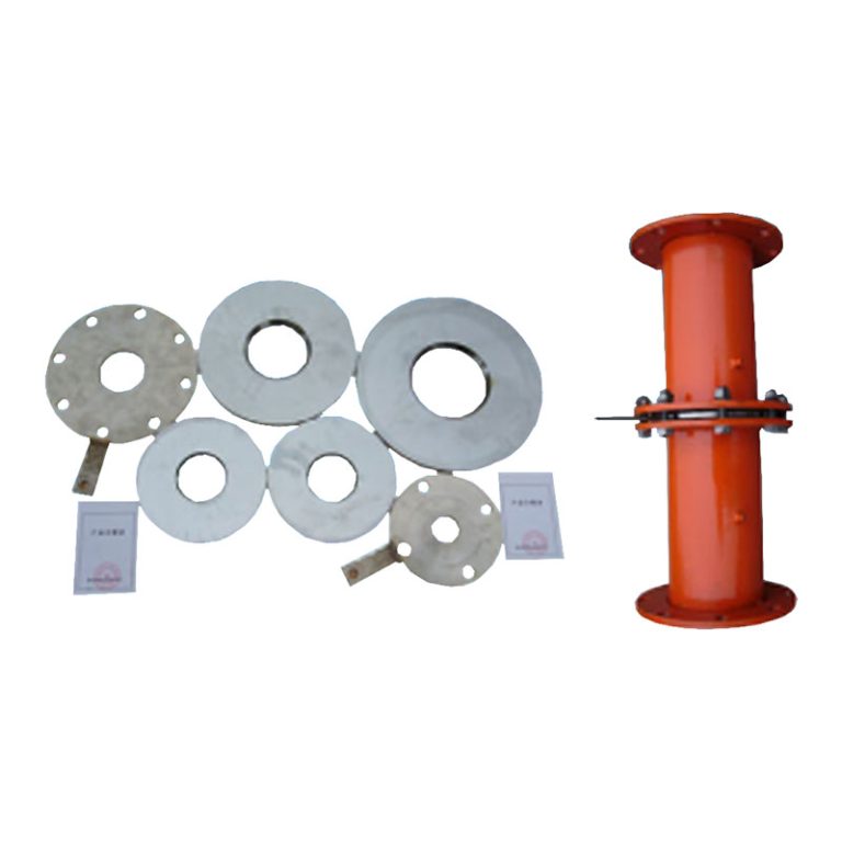
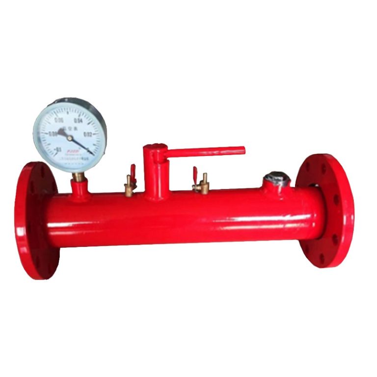
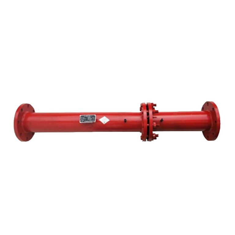
The differential pressure orifice flowmeter is a supporting equipment designed for calculating the amount of gas pumped in coal mines according to the characteristics of coal mine gas extraction. Its simple structure, easy installation and use, high measurement accuracy, is the most economical device for measuring gas flow.
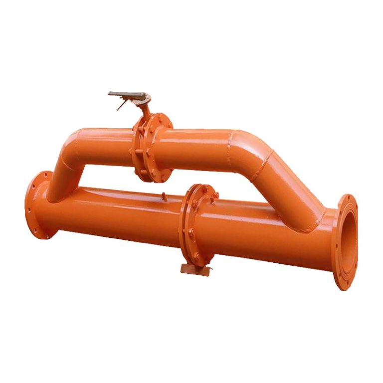
This series of differential pressure orifice flowmeters can add a bypass in the design and production according to user requirements, and install a valve on the bypass. When measuring the flow rate of the gas pipeline, close the valve in the bridge pipe section so that the medium completely passes through the orifice plate to achieve the purpose of measurement; During normal gas pumping, in order to reduce the pumping resistance, the valve in the bridge pipe section is opened.
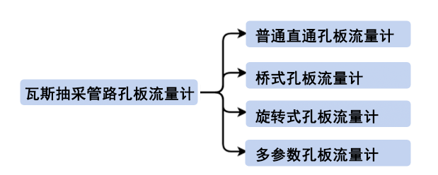
Product implementation standards
| GB/T2624-2006 "Measurement of full pipe fluid flow using a pressure differential device installed in a circular cross-section pipe" | Q/KMZN 00-2016 "Orifice Plate Processing Inspection Standard" |
| JJG640-1994 "Calibration Regulations for Differential Pressure Flow meters" |
Working Principle
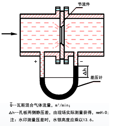
The differential pressure orifice flowmeter measures the gas flow rate of the pipeline by means of the radial pressure method. When the continuous flow of fluid through the throttling device in the pipeline will increase, the static pressure difference between the upstream and downstream sides of the throttling device appears, and there is a constant relationship between the flow rate and the pressure difference, so the pressure difference is measured by the differential pressure gauge, and then the flow rate of the fluid can be calculated by the formula. The schematic diagram is shown in the figure below
